Sauer Danfoss Series 15 Tandem Pump
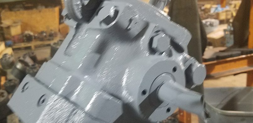
Sauer Danfoss Series 15 Tandem Pump
March 17, 2022 Comments Off on Sauer Danfoss Series 15 Tandem PumpThese diagrams and charts show the charge pump, relief valve, trunnion shaft seal and so much more.
To do minor repairs
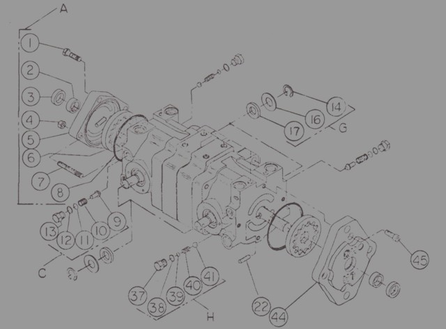
Charge Pump A
NO. Description of Part QTY 1 screw hex head 2 2 bearing – needle 2 3 seal – lip 2 4 nut – hex 2 5 housing – charge pump 1 6 charge pump – gerotor 2 7 stud 2 8 oring 2 22 pin drive 2 44 housing – charge pump 1 45 screw – soc. hd. 4
Trunnion Shaft Seals G 14 ring – retaining 4 16 washer 4 17 seal – lip 4
Charge Pump Valve H 37 plug -hex head 2 38 oring 2 39 shims A/R 40 spring 2 41 ball 2
Implement Relief Valve C 9 cone 2 10 spring 2 11 shims A/R 12 oring 2 13 plug – hex head 2
Circuits
On these pumps you have two variable displacements that operate an ordinary shaft. Every single pump is made to be intertwined in a closed loop to a fixed displacement motor. Every pump works on it’s own (not the shaft) and has singular circuits, which are: charge pump, charge check valves, charge relief valve and implement relief valve.

If you need further info on this unit call us at 800-361-0068
sales@htsrepair.com