Denison Goldcup 8A Mechanical Shaft Seal Installation
November 30, 2022Comments Off on Denison Goldcup 8A Mechanical Shaft Seal Installation
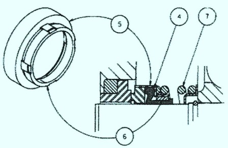
Make sure to put the pump so that the port block inlet and outlet pads are pointing down, so that you can put in the shaft and bearing assy in the mounting flange/cradle. Make your unit doesn’t have any burr edges on shaft seal that will affect the shaft. Next put on the snap ring in the mounting flange in the shaft assy. You will need to make sure it is seated in the groove good. The seal kit is only sold as a whole kit. On your seal that is lapped and the ring, have a finish on them that should not be damaged in any way. Put the spring retainer over the shaft and snug up on the retaining ring on the shaft assy. And the spring needs to go upon the retainer ring. It will need some grease of some sort to go inside the surface of teh rubber friction ring. Place the shell containing the ribber friction ring/carbon ring over the shaft so the carbon ring is clearly visible. Put more grease on the seal retainer that has the lapped side so it is matched up with the carbon ring. Put the seal retainer assy and oring over the shaft so the lapped side is up against the carbon side. Put four gaskets on the screws and put in the seal retainer. Push the seal retainer just enough to start the screws to be tightened up in a clockwise position til all screws are tightened up to the same amount of pressure to each one. Some controls have orings instead of gaskets in older models. And cast iron cover have different gaskets also.
To put the seal, put in two spacers on the two screws and put in thru the balance plate and servo stem. Put the parts right thru the hole in the side of the housing assy and put in the screw over the tapped holes in the rocker cam. Push the parts right up to the cam and sequentially tighten them evenly so it holds the assy together tight. Put the gasket on the control cover assy. If it has a powdered metal cover it uses and oring only. Your input cover assy has to be put in on the right hand side of the housing on pumps that have a B in the code and output cover on the right hand side if it has an A in the code. Put some type of grease on the oring grooves on the bottom side of the valve block. Next put in orings in the grooves and put the valve block on the side that matches the area of the port block. Make sure the oring stay where they are suppose to be and put in the screws and evenly tighten them up.
If you have any questions, call us at 800-361-0068