Sundstrand Sauer Danfoss Series 40 Integral Charge Pump Part 4
Sundstrand Sauer Danfoss Series 40 Integral Charge Pump Part 4
April 4, 2016 Comments Off on Sundstrand Sauer Danfoss Series 40 Integral Charge Pump Part 4At our Hydrostatic Pump Repair Site, we offer many types of Hydrostatic Transmission Repair and information relating to Hydrostatic Parts
Today we will discuss;
Sundstrand Sauer Danfoss Series 40 M46 Integral Charge Pump
Part 4 Tandem Pump
Before you do the assembly, grease the gerotor assembly with clean hydraulic oil and the o rings get greased with petroleum jelly.
If your unit is equipped with (15.6cc/rev) charge pumps, put the front gerotor spacer plate into the front pump housing.
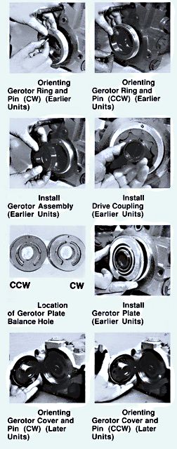
On the earlier models the rotation of the charge pump was made aware of by the position of the gerotor ring. On gerotor covers on the previous models you could see that it used a locating pin in the front pump housing. Also,the gerotor plate or gerotor cover has a pressure balance hole that needs to be put on the outlet side of the charge pump, opposite the charge inlet port. Other gerotors plates or covers are used for clockwise and counter clockwise rotation groups.
Put in the drive pin into the drive shaft coupling. Next goes the gerotor assembly into the gerotor ring or cover, then the gerotor assembly into the gerotor ring or cover into the coupling. You will need to make sure the drive pin matches the slot in the gerotor.
Pumps that have a separate gerotor ring and spacer plates, put the gerotor ring into the pump housing, adapting it for the input shaft rotation direction. The locating pin hole in the gerotor ring must be closest to the control for clockwise input rotation and away from the control for counter clockwise input rotation. Put the locating pin into the gerotor ring and pump housing. The gerotor plate goes onto the gerotor ring. The pressure balance hole in the gerotor plate has to be located at the other end of the charge pump inlet. Pun in the necessary o rings on the inner side, in the groove on the back of the gerotor plate. Then put the outer o ring into the rear pump housing.
If your pump has a one piece gerotor cover, put the locating pin into the gerotor cover. Put the gerotor cover (with the gerotor & coupling) into the pump housing, align it for the correct input shaft rotating direction. The locating pin in the gerotor cover needs to be the closest to the control clockwise input rotating and away fro the control for counterclockwise input rotation. The pressure balance hole in the gerotor cover has to be located at the other end of the charge pump inlet. Make sure the drive pin connects to the slot in the gerotor. Put in the outer and inner o rings in the grooves on the back of the gerotor cover.
The pumps that have date codes of 87-34 and up, need to use a altered gerotor cover and a smaller out o ring. For these models, put the out o ring into the groove on the gerotor cover and lubricating it with petroleum jelly.
This concludes the topic of the integral charge pumps, but if you have a comment or need to ask a question. Please leave us a comment or you can call
800-361-0068
email: sales@hydrostatic-transmission.com