John Deere Crawler 755B Assemble Hydrostatic Manifold Valve

John Deere Crawler 755B Assemble Hydrostatic Manifold Valve
May 2, 2016 Comments Off on John Deere Crawler 755B Assemble Hydrostatic Manifold ValveAt our Hydrostatic Pump Repair Site, we offer many types of Hydrostatic Transmission Repair and information relating to Hydrostatic Parts
Today we will discuss:
John Deere Crawler 755B – Assemble Hydrostatic Manifold Valve
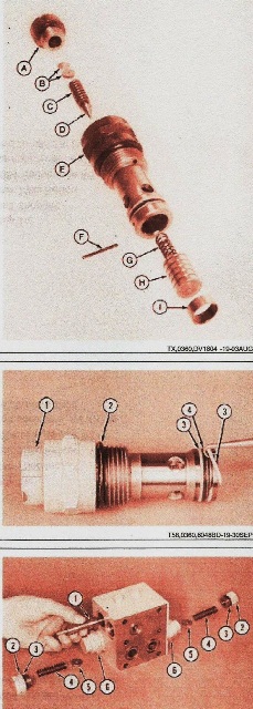
Put in the same amount of shims (B) that were taken out to level out the original pressure settings. Diagram 1
Put in parts (A- I)
A – Plug with o ring
B- Shim (as required)
C – Spring
D – Poppet
E – Relief Valve
F – Pin
G – Spring
H – Valve Spool
I – Spacer
Put in new o rings ( 2 & 4) and backup rings (3) on high pressure relief valve (1) Diagram 2
1 – High Pressure Relief Valve
2 – O Ring
3 – Backup Ring (2 used)
4 – O ring
Put in high pressure relief valves (6). Diagram 3
Put in the shuttle valve spool parts (1-5)
1 – Shuttle Valve Spool
2 – Plug (2 used)
3 – O Ring (2 used)
4 – Spring (2 used)
5 – Special Washer (2 used)
6 – High Pressure Relief Valve (2 used)
If you need any questions answered about this topic, please leave us a comment or call us at 800-361-0068
Email: sales@hydrostatic-transmission.com