Series 8 Air/Gas Boosters
Series 8 Air/Gas Boosters
April 3, 2023 Comments Off on Series 8 Air/Gas Boosters
Size Specs
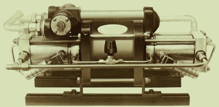
8AGD-5 (line drawing) 8AGD-14 (shaded area) 8AGT-5/14 (light orange area) They are all about the same. The gas inlet, some of the plumbing and where the muffler is on the unit are some of the differences. Also the port size is included in that list of differences.
Control Features
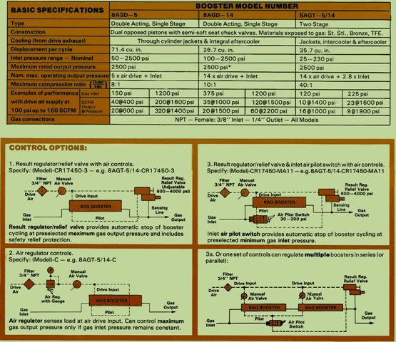
Air Drive Unit
If you have working pressure 40-130 psi Media Compressed air, nitrogen, natural gas, CO2 Port input 3/4″ npt female Exhaust 1/2″ npt female – 2 ports mufflers are a given. Exhaust is piped in from exit on cooling unit and you can make it longer if you wanted to. Pilot cycling valve 1/8″ npt female hooks up from drive input comes with

Chart on Performance
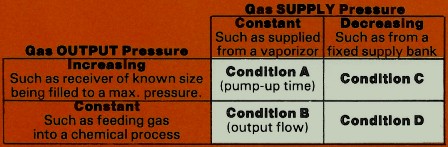
Uses for A, B, C or D
Output Flow
B is for all the models. Curves – booster speed lower with pressure load.
Pump UP
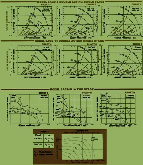
A is for 8AGD-14 and 8AGD-5 Gas inlet curve are in orange. This curve is a receiver size of 1 cu ft. and the gas inlet pressure is stable in the booster before you start it. If the receiver differs from 1 cu ft. the time will be relative.
Drive Air Use (8AGD-5 & 8AGD-14)
Charts at the bottom
A – pump up time. B – Output flow
(8ADT-5/14) – scfm. are the italicized number for curves in 7, 8 & 9.
2500 PSI
Double acting single and two stage units that are high flow
Your drive lube is small, no moving parts. No electrical input so it helps with overload protection.
If you need more info on this unit, call us at 800-361-0068
sales@htsrepair.com