September 13, 2022Comments Off on Vickers PVB 90 Axial Piston Pump
Variable & fixed displacement
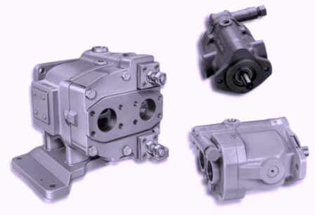
There is an added feature of a foot mounting…you can see by the dotted line on the diagram. There is also a base mounting by having four tapped holes in the bottom part of the pump. A. = When your unit is operating, don’t take the screw out past the measurement on the diagram. Black triangle means that the location of the tapping for the lifting eye bolts ..you have two at the shaft end and one on the rear of it. Shaft rotation on a RH use Inlet port A and use B on outplet port. Shaft rotation on LH use B on inlet port and A on outlet port. Tappings in base of pump. A.= When unit is operational don’t let the compensator screw go past the measurement indicated on the diagram. B. = these are compensator placement: PVB5/6 LSV …LH rotation models PVB 10/15 RSY ..RH rotation models OVB20/29 SY…RH and LH rotation models C. = Adjusting Rod..least amount of delivery placement, make sure screw is right up against the nut. Don’t let the screw go below the nut. D. = Compensator placement for PVB5/6 RH rotation models…..PVB10-15 LSY…LH rotation models
If you need further information on these types of units or any other Vickers Products, give us a call at