Denison Hydraulic Goldcup Model C/A Barrel & Auxiliary Drive Shaft Assembly
August 8, 2018
Denison Hydraulic Goldcup Model C/A Barrel & Auxiliary Drive Shaft Assembly
Instructions for Barrel/Auxiliary Drive Shaft Assy
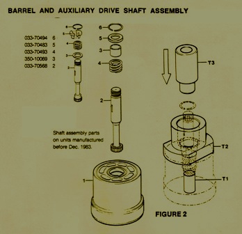
Put the barrel (1) in a pres with the large end turned down & put in too fig. T-1 in the splined shaft hole in the barrel.
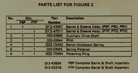
The stop (3) & spring (4) go over the shaft (2) in the same way it is shown in diagram.
Put the shaft (2) into the barrel (1) and let it lie on tool fig. T-1. Seating the spring retainer (5) over the shaft (2) and up against spring (4).
Gently put the tool fig. T-2 with the large end of the tapered hole up and over the shaft (2) and right up against the barrel (1) face. Then put in the ring (6) around the shaft (2) and in the tool.
Place the ring wit the gap within 5/8″ of the notch in the barrel for simpler removal.
Position tool fig. T-3 over the shaft (2)with the small end snug up against the ring (6). Push on the end of the assembly tool and place the ring (6) in the groove in the barrel (1).
Take out the assembly tools. Look to be certain the ring is pressed in there correctly. Make sure the barrel is not marked or damaged in any way.
If you need further assistance with this, please call us at
800-361-0068
sales@hydrostatic-transmission.com


