Sundstrand Sauer Danfoss Series 20 Circuits & Performance Curves

Sundstrand Sauer Danfoss Series 20 Circuits & Performance Curves
April 7, 2016 Comments Off on Sundstrand Sauer Danfoss Series 20 Circuits & Performance CurvesAt our Hydrostatic Pump Repair Site, we offer many types of Hydrostatic Transmission Repair and information relating to Hydrostatic Parts
Today we will discuss:
Sundstrand Sauer Danfoss Series Circuits and Performance Curves Variable Displacement Pump – Variable Displacement Motor Traits
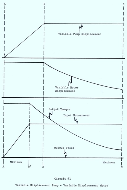
Circuit #1
Peak efficiency takes place at mid speed.
The performance is at it’s best over a broad part of the speed range.
Output speed is taken in by both pump displacement and motor displacement. (output speed)
For the best case scenario of hydraulic sizing, the pump is nearly one half the size (displacement) of the motor.
This particular circuit has the widest output speed range.
Performance Curves
Point A
The variable displacement pump is at its lowest displacement, there is no flow and no transmission output. The variable displacement motor is in its highest displacement. This gives the greatest starting torque at the motor output shaft and in return produces the entire range of the transmission.
Point B’
This tells the point at which the input horsepower reaches its highest potential. It shows that the highest level of horsepower can be obtained before the pump succeeds at getting the best angle or flow. Pressure was at maximum up to B’ and falls off between B’ and B, and is constant from B to C. Involving points B’ & C’ the transmission is at constant horsepower transmission, thus taking over working pressure conditions.
Point B
The pump displacement has gotten to maximum. The motor displacement is at constant, but the motor output speed has increased. If the given pressure, has not increased in output horsepower is likely since the horsepower is a function of the flow and pressure. It reached its maximum pump flow at Point B. The motor displacement goes from high to low with the resulting decline in output torque and increase the output speed.
Point C
The transmission has gotten to its highest output speed and the horsepower output is the same as it was at Point B’. This could be used to explain a situation in which a variable pump and variable motor is used to move a crawler tractor. When two transmissions of the same size, one can drive each track. When this happens it would provide the following:
Self governing control of each track for steering.
Tracks can used in different directions for spin turns.
Unlimited speed control by interchanging the pump and motor displacement.
Peak output torques for starting, bulldozing and towing.
Maximum speed for traveling.
When using variable displacement pump/motor verses a fixed displacement pump/motor is: when the output speed might be varied, thus making lower circuit flow than is possible with a fixed displacement pump/motor. In return smaller pumps would have to be used.
The variable pump/motor combo gives you the highest return at mid speed range rather than at the greatest amount of speed range, as with the variable pump and fixed motor combo.
If you need more info or help understanding this topic, please leave a comment or call us at 800-361-0068
And you can email us at sales@hydrostatic-transmission.com