Manual Displacement Control
Manual Displacement Control
January 29, 2016 Comments Off on Manual Displacement ControlTopic today discusses Manual Displacement Control
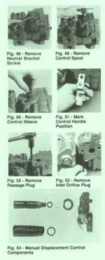
Before dis assembly, note the position of the control handle and neutral bracket as either :up’ or “down”.
Remove the screw and washer or flange head screw retaining the neural bracket to the housing using a 7/16″ or 3/8″ wrench.
The spool (with neutral bracket, neutral spring ,control handle and nut) can now e removed from the unit.
Remove the control sleeve from the unit by carefully gripping the end of the sleeve with pliers and pulling out.
If it is necessary to remove the control handle and neutral bracket from the spool, remove the nut from the spool using a 1/2″ wrench. Take out the lock washer. Disengage the neutral spring from the handle and take the handle from the spool. The neutral spring and neutral bracket can now be removed from the spool.
To get access to the control inlet orifice, take the plug located between the control sleeve bore and the filter adapter, using a hex wrench 9/16″ on pumps with code 86-13 or below, or an internal hex wrench 3/16″ on pump with date code 86-14or above. Remove the inlet orifice plug using an internal hex wrench 1/8″ for pumps with date code 86-13 or below, 5/32″ for pumps with date code 86-14 or above.
After dis assembly, all parts should be thoroughly cleaned in a solvent. Replace O rings and backup rings. Lightly grease all o rings with a small amount of clean petroleum jelly prior to assembly.
Hope this topic was helpful today.. always remember to keep parts from contaminants, before reinstalling.
800-361-0068
hydrostatic-transmission.com